Undersized cables are the most common and most dangerous mistake in solar installations. A cable that is too thin for the current it carries wastes energy as heat, creates a fire risk at the terminals, and causes voltage drop that reduces the power reaching your battery or inverter. This guide covers every cable run in a solar system with the sizing formulas, the voltage drop limits you must stay within, and a reference table for the most common configurations. Our Wire Gauge Calculator automates every calculation below.
Why Cable Sizing Matters in Solar
Solar systems run at low DC voltages — typically 12V, 24V, or 48V. Low voltage means high current for any given power level: a 1,000W load at 12V draws 83 amps, but the same load at 48V draws only 21 amps. High current demands thick cables, and thick cables cost money and are difficult to route. Getting the cable gauge exactly right — not oversized (wasting money) and not undersized (wasting energy and creating risk) — is one of the most impactful engineering decisions in the entire system.
The consequences of undersizing are not theoretical. A cable carrying 50 amps through a wire rated for 30 amps heats up. At best, you lose 5 to 15 percent of your solar production as waste heat in the cable. At worst, the insulation melts, the terminal connection loosens from thermal cycling, and the cable becomes an ignition source. Every solar fire investigation starts by checking the cable sizes.
The Three Cable Runs in a Solar System
Every solar installation has three DC cable runs, and each has different sizing requirements because the current and acceptable voltage drop differ at each stage.
Run 1: Solar panels to charge controller. This cable carries the panel’s output current at the panel’s operating voltage (Vmp, typically 17 to 40V per panel depending on configuration). The current is determined by the panel’s Imp rating multiplied by the number of parallel strings. Voltage drop limit: 3 percent maximum (industry standard for the PV-to-controller run). Typical currents: 8 to 30 amps for residential systems.
Run 2: Charge controller to battery bank. This is almost always the highest-current cable in the system because the MPPT controller converts the panel’s higher voltage to the battery’s lower voltage, increasing the current proportionally. A 400W array producing 22 amps at 18V becomes 33 amps at 12V after MPPT conversion. Voltage drop limit: 1 percent maximum (because the charge voltage must be precise for proper battery charging — even 0.3V of drop can prevent the battery from reaching full absorption voltage). This cable is typically the shortest run but the thickest gauge.
Run 3: Battery bank to inverter. This cable carries the full discharge current of the inverter. A 3 kVA inverter at 12V draws up to 250 amps at full load. At 48V, the same inverter draws 63 amps. Voltage drop limit: 1 to 2 percent. This cable is usually the most expensive single component in a 12V system — another reason why higher battery voltages save money. Our 12V vs 24V vs 48V guide explains the full cost impact.
The Cable Sizing Formula
The formula for minimum cable cross-section in mm² is: Cable mm² = (2 x Length in meters x Current in amps) / (Voltage drop in volts x Conductivity). For copper, conductivity is 56. The “2x” accounts for the total round-trip distance (positive wire out, negative wire back). In AWG terms, you calculate the mm² and look up the corresponding AWG gauge.
The voltage drop in volts is calculated from the percentage limit: Voltage drop (V) = System voltage x Percentage limit. For a 12V system at 3 percent: 12 x 0.03 = 0.36V allowable drop. For a 48V system at 3 percent: 48 x 0.03 = 1.44V. This is why higher voltage systems tolerate thinner cables — the same percentage drop allows a larger absolute voltage loss.
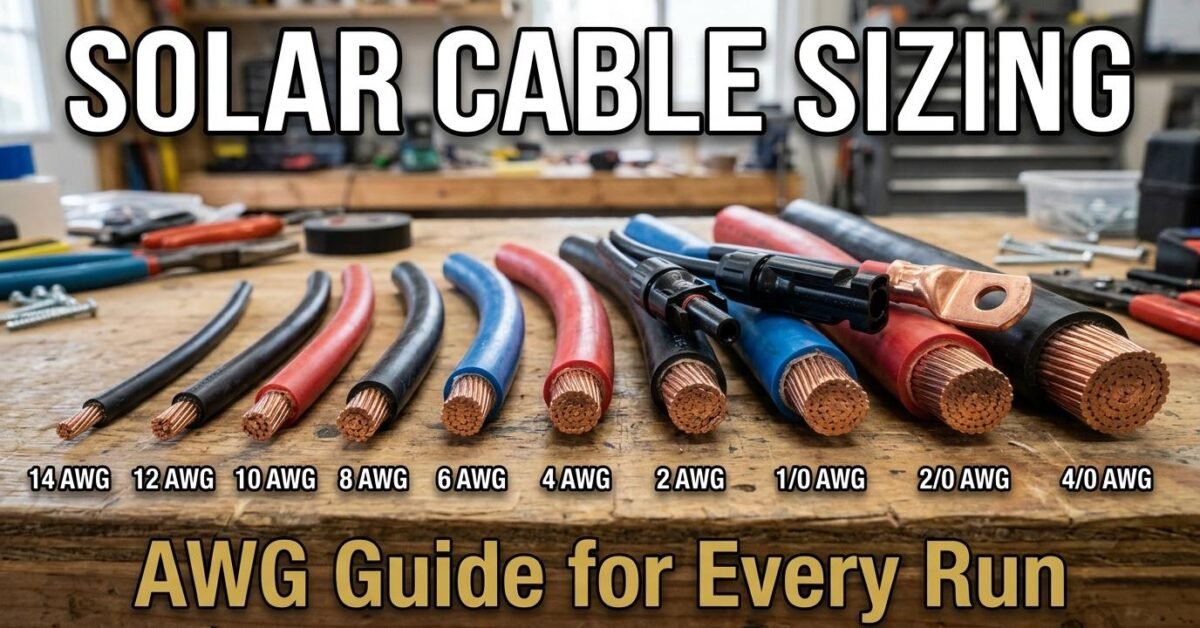
AWG Quick Reference Table
| AWG | mm² | Max Amps (30°C) | Typical Use in Solar |
|---|---|---|---|
| 14 AWG | 2.1 | 15A | Small panel to controller (under 200W at 12V) |
| 12 AWG | 3.3 | 20A | Panel to controller (200-400W) |
| 10 AWG | 5.3 | 30A | Panel to controller (400-800W), short controller-to-battery runs |
| 8 AWG | 8.4 | 40A | Controller to battery (medium systems), short inverter feeds |
| 6 AWG | 13.3 | 55A | Controller to battery (large 12V), battery to inverter (small) |
| 4 AWG | 21.2 | 70A | Battery to inverter (12V systems up to 1 kVA) |
| 2 AWG | 33.6 | 95A | Battery to inverter (12V systems up to 1.5 kVA) |
| 1/0 AWG | 53.5 | 125A | Battery to inverter (12V systems up to 2 kVA) |
| 2/0 AWG | 67.4 | 145A | Battery to inverter (12V 3 kVA or 24V 5 kVA) |
| 4/0 AWG | 107 | 195A | Battery to inverter (12V 5 kVA — the thickest standard cable) |
These ampacity ratings assume 30°C ambient temperature and copper conductors. Derate by 15 to 20 percent for higher temperatures (hot attics, direct sun exposure on conduit), and always verify against your local electrical code (NEC in the US, IEC elsewhere).
Worked Example: 400W System at 12V
Panel to controller (3m run, 3% drop limit): Two 200W panels in parallel produce about 22A at Vmp ~18V. Allowable drop: 18 x 0.03 = 0.54V. Cable mm² = (2 x 3 x 22) / (0.54 x 56) = 132 / 30.2 = 4.4 mm² minimum. That is 10 AWG (5.3 mm²). Our Wire Gauge Calculator confirms: 10 AWG at 3m gives 2.5% drop — within limit.
Controller to battery (1m run, 1% drop limit): The MPPT controller outputs about 33A at 12V charge voltage. Allowable drop: 14.4 x 0.01 = 0.144V. Cable mm² = (2 x 1 x 33) / (0.144 x 56) = 66 / 8.1 = 8.1 mm² minimum. That is 8 AWG (8.4 mm²). At just 1 meter, this seems oversized, but the 1 percent limit on the charge cable is non-negotiable — even a small drop prevents the battery from reaching proper absorption voltage.
Battery to inverter (1.5m run, 2% drop limit): A 1.5 kVA inverter at 12V draws up to 125A at full load. Allowable drop: 12 x 0.02 = 0.24V. Cable mm² = (2 x 1.5 x 125) / (0.24 x 56) = 375 / 13.4 = 28 mm² minimum. That is 2 AWG (33.6 mm²). This thick cable is why most systems above 1.5 kVA should use 24V or 48V batteries — the same inverter at 24V draws only 63A and needs just 6 AWG.
Common Cable Sizing Mistakes
Using the short run as an excuse for thin cable. A 0.5-meter cable carrying 100 amps still needs to be thick — the current does not care about the distance. Short runs reduce voltage drop but do not reduce the ampacity requirement. The cable must be rated for the current regardless of length.
Ignoring the round-trip distance. Current flows out on the positive wire and returns on the negative wire. A 3-meter cable run is actually 6 meters of total conductor length for voltage drop calculation. The “2x” in the formula accounts for this. Forgetting it undersizes the cable by half.
Using the panel’s Isc instead of Imp. Short-circuit current (Isc) is higher than the maximum power current (Imp), but the cable only carries Imp during normal operation. However, NEC requires cables to be rated for 125 percent of Isc — not Imp — as a safety factor. For sizing purposes, use Imp for voltage drop calculation but verify the cable’s ampacity rating exceeds 1.25 x Isc.
Calculate Your Cable Size
Our Wire Gauge Calculator computes the minimum AWG and mm² for any cable run — enter the current, length, voltage, and acceptable drop percentage, and it outputs the gauge with the actual voltage drop at that gauge. Use it for every cable run in your system, and check the results against the worked example above to build confidence in the numbers. If you are building a complete system, the Solar System Calculator sizes panels, battery, inverter, and controller in one pass, and the Battery Charge & Discharge Calculator determines your charge current and MPPT specifications.