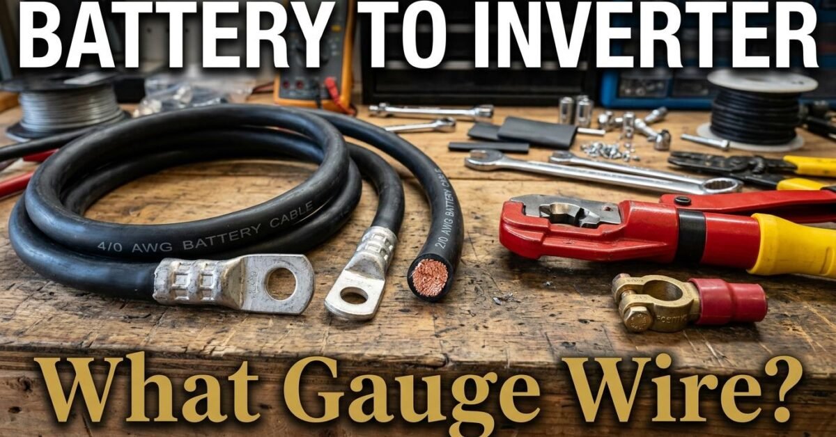
The cable from battery to inverter carries the highest current in any solar or backup system. A 3 kVA inverter at 12V draws 250 amps at full load — requiring cable as thick as your thumb. Undersizing this cable is the most dangerous wiring mistake you can make because the full discharge current flows through it continuously during operation. This guide sizes the cable for every common inverter and battery voltage combination.
Cable Sizing Table: Battery to Inverter
The following table assumes a 1-meter cable run with a 2 percent maximum voltage drop. For longer runs, go one size thicker per additional meter.
| Inverter | 12V Battery | 24V Battery | 48V Battery |
|---|---|---|---|
| 500W (0.5 kVA) | 8 AWG (44A) | 12 AWG (22A) | 14 AWG (11A) |
| 1,000W (1 kVA) | 4 AWG (88A) | 8 AWG (44A) | 12 AWG (22A) |
| 1,500W (1.5 kVA) | 2 AWG (132A) | 6 AWG (66A) | 10 AWG (33A) |
| 2,000W (2 kVA) | 1/0 AWG (175A) | 4 AWG (88A) | 8 AWG (44A) |
| 3,000W (3 kVA) | 2/0 AWG (263A) | 2 AWG (132A) | 6 AWG (66A) |
| 5,000W (5 kVA) | Not practical | 1/0 AWG (219A) | 4 AWG (110A) |
| 8,000W (8 kVA) | Not practical | Not practical | 2 AWG (175A) |
| 10,000W (10 kVA) | Not practical | Not practical | 1/0 AWG (219A) |
Notice how quickly 12V becomes impractical above 2 kVA. A 3 kVA inverter at 12V needs 2/0 AWG cable — extremely thick, stiff, and expensive. The same inverter at 48V uses a manageable 6 AWG. This is the strongest practical argument for higher battery voltages in any system above 1.5 kVA. Our 12V vs 24V vs 48V guide covers the full cost and engineering comparison.
The Sizing Formula
Current (amps) = Inverter watts ÷ Battery voltage ÷ Inverter efficiency (0.95). Minimum cable mm² = (2 × Length × Current) ÷ (Allowable voltage drop × 56). Allowable drop = Battery voltage × 0.02 (2 percent). Use our Wire Gauge Calculator for exact results at any configuration.
Why 2 Percent Voltage Drop — Not 3 Percent
The battery-to-inverter cable has a stricter drop limit than the panel-to-controller cable (3 percent) because the inverter needs stable input voltage to operate correctly. If battery voltage is 12.0V and the cable drops 0.5V, the inverter sees only 11.5V — which may trigger a low-voltage shutdown even though the battery has plenty of charge remaining. A 2 percent limit on 12V allows only 0.24V of drop, keeping the inverter well within its operating window. At 48V, 2 percent allows 0.96V — much more forgiving.
Cable Length Matters More Than You Think
Every additional meter of cable run at high current dramatically increases the required gauge. A 1 kVA inverter at 12V with a 1-meter cable needs 4 AWG. Move the battery 3 meters away and you need 2 AWG. At 5 meters you need 1/0 AWG — a cable that costs three to five times more per meter. Always install the battery bank as close to the inverter as physically possible. One meter or less is ideal. For our complete cable guide covering all three runs in a solar system, see the Solar Cable Sizing Guide.
Cable Termination and Connection Quality
The battery-to-inverter connection is the highest-current junction in your system. Use hydraulic-crimped ring terminals or compression lugs — never soldered connections, which develop high-resistance joints under vibration and thermal cycling. Torque all terminal bolts to the manufacturer’s specification (typically 8 to 12 Nm for M8 studs) and apply a thin layer of dielectric grease or anti-oxidant compound to prevent corrosion. Re-torque all battery connections after the first month of operation and annually thereafter — thermal cycling loosens connections over time, and a loose high-current connection is an arc-flash hazard.
Cable Routing Best Practices
Route the positive and negative cables along the same path to minimize electromagnetic interference. Use cable clips or conduit to secure the cables every 30 to 50 centimeters — unsecured thick cables can shift from vibration (especially in RV and marine installations), stressing the terminal connections. Never run battery cables near heat sources (inverter exhaust, engine compartments) without high-temperature rated insulation. Standard PVC insulation is rated to 75 degrees Celsius; silicone-jacketed cable handles 150 degrees and is the correct choice for any run near heat-generating components.
Fusing the Battery-to-Inverter Cable
A fuse or circuit breaker must sit between the battery and inverter, as close to the battery positive terminal as possible. The fuse rating should be above the maximum continuous current but below the cable’s ampacity. For a 3 kVA inverter at 12V drawing 263A on 2/0 AWG cable (rated 265A): a 300A ANL fuse is correct. The fuse protects against cable overheating if the inverter has an internal fault — without it, a short circuit draws thousands of amps from the battery, melting the cable instantly. Never skip this fuse.
Terminal Types for Heavy Cable
For cables 4 AWG and thicker, use copper ring terminals (also called lug terminals) crimped with a hydraulic crimper — never soldered. Solder creates a brittle joint that fails under vibration and thermal cycling. The ring terminal internal diameter must match the cable gauge, and the bolt hole must match the battery or inverter terminal stud (typically M8 or 3/8 inch). After crimping, apply adhesive-lined heat shrink tubing over the crimp for waterproofing and strain relief. This detail seems minor but is the difference between a connection that lasts 20 years and one that develops resistance, heats up, and eventually fails at the worst possible moment.